Newer Drives
Newer drives do not have jumper settings that can be changed.
All public information is in the data sheets on the support.wdc.com Product Pages.
Need more help?
Answer ID 20968: Internal Drive Advanced Format 4k Sector Size Support and Information
Legacy Drives and Window Operating System Support
IMPORTANT:
Support for Discontinued and Legacy drives made before 2018 has ended.
View the Use of Third-Party Software or Websites disclaimer.
Western Digital Support cannot help with third-party software or hardware.
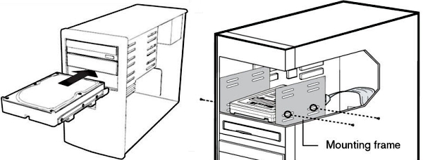
Physical Installation
 |
Critical: Special handling is needed to protect drives from damage. |
- Put the drives in.
- Desktop Drives: The drive can be put in a standard 3.5" drive bay.
Use all mounting screws prevent vibration and provide more grounding. - Mobile Drives: Drive installation will vary by system.
Contact the system maker for mounting instructions.
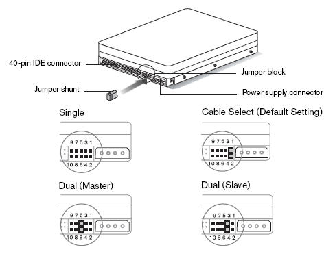
- Set the jumpers.
Jumper settings will vary by model. There is no need to change the default jumper setting to use the drive. The drive label will show the exact jumper settings it supports.
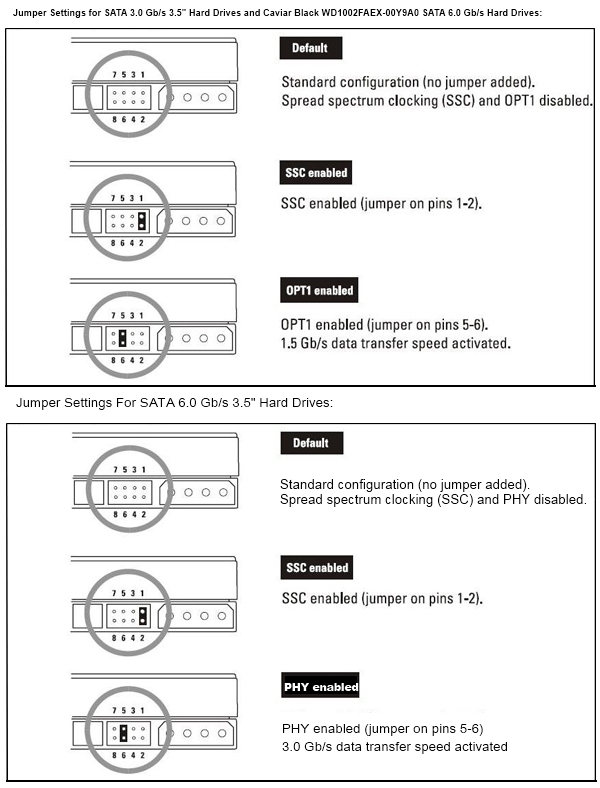
Serial ATA (SATA) I, II, and 6 Gb/s Hard Drive Jumper Settings for 3.5" Drives
IMPORTANT:
Caviar Black drives that have a model number WD1002FAEX-00Y9A0 use the SATA 3.0 Gb/s pin layout.
Setting Jumpers 5 & 6 on these drives will enable OPT1 which sets the drive to 1.5 Gb/s.
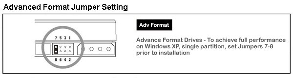
Advanced Format Special Jumper Setting (select 3.5" ADF drives only)
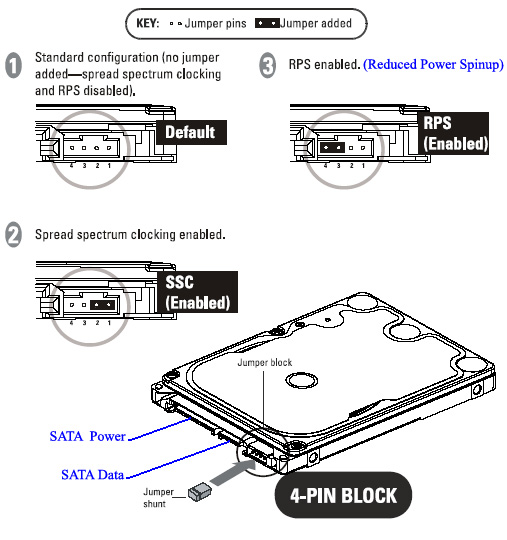
SATA Mobile Hard Drive Jumper Settings
EIDE (PATA) Desktop Hard Drive Jumper Settings
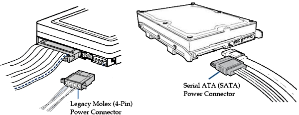
- Attach the power cable.
Use the SATA power connector or the legacy ATA-4-pin (Molex) power connector on the back of the drive.
Critical:
Do not connect both the SATA and the legacy ATA power cable to the drive at the same time. This will damage the drive.
SATA Drives
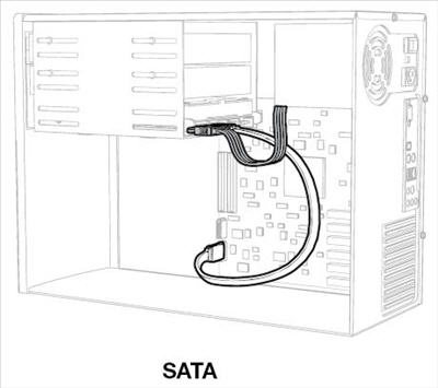
- Attach the EIDE (PATA) or SATA interface cable.
There are two ways to do this.
- Connect to a SATA host adapter card in the system.
- Connect to a Serial ATA connector on the motherboard.
Either end of a standard SATA cable can be connected to the drive.
Connect the cable to the drive.
Connect the other end to the SATA host adapter card, or motherboard.
Make sure the cable is no longer than 39 inches to minimize line noise.Drive connected Motherboard
EIDE (PATA) Drives
- Connect the cable to the drive.
- Only drive on cable?
Connect the black connector of the EIDE (PATA) interface cable to the drive. - Two or more drives on cable?
Jumper the bootable drive as Master, and the other drive as Slave.
Connect the Master drive to the black connector of the EIDE (PATA) interface cable.
Connect the Slave drive to the gray connector.
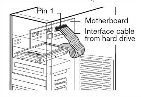
- Connect the IDE Interface Cable to the Motherboard.
Attach the blue end of the cable to the 40-pin connector on the board.
Match Pin 1 of cable to the connector on the board.
- Power on the computer.
- Replace the system cover.
Reconnect the power cord.
Press the power button. - Run CMOS Setup and onfigure the BIOS to see the drives.
Check the system or motherboard for instructions.
View the Use of Third-Party Software or Websites disclaimer.
Western Digital Support cannot help with third-party software or hardware. - Restart the computer.
- Install the Operating System or configure it to see the drive.
- Power off the computer.
Remove the power cable.
Press the power button on.